Designing for the Zinc Bath: A Drawing-Office Guide to Vent and Drain Detail
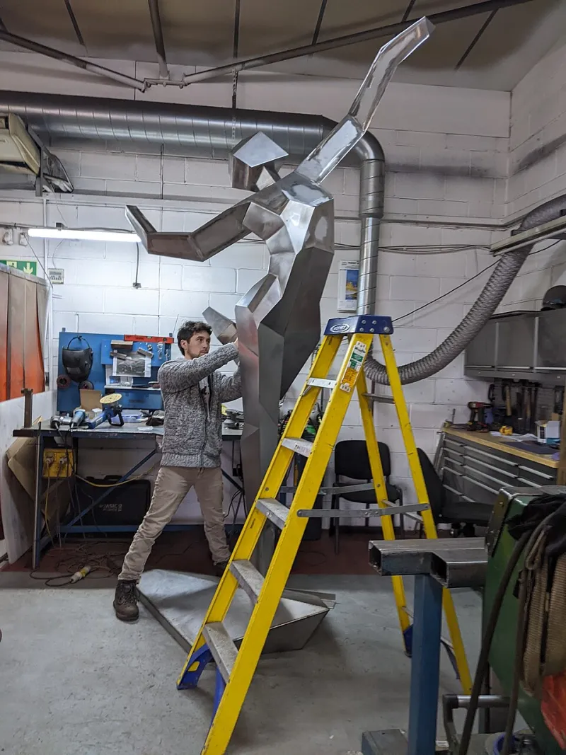
Photo: The Artist 26, CC BY-SA 4.0, via Wikimedia Commons
Hot-dip galvanising is often specified as a line item on a fabrication drawing, yet it is not a surface treatment applied after the event. It is an immersion process. The steel is cleaned, pickled, fluxed, dipped in molten zinc and withdrawn. Every closed volume, every overlapping plate and every internal baffle has to let air out and process liquids drain. If the detailing does not allow that, the galvaniser cannot correct it at the bath. The drawing office has to solve it first.
For trade buyers and project engineers procuring bespoke metalwork in the UK, the practical question is not whether galvanising is specified, but whether the fabrication has been designed for it. That means agreeing vent and drain detail early, inspecting it before dispatch and keeping a clear record of what was decided. The alternative is a familiar sequence: trapped pickling liquid, uneven coating, distortion, rejected parts and an awkward conversation about responsibility.
The process sets the detailing rules
A hot-dip galvanising line is not a paint shop. Components are immersed in cleaning and pickling solutions, then in molten zinc at around 450°C. Air pockets prevent zinc from reaching internal surfaces. Trapped acid or rinse water can weep out later, staining the coating or causing blistering. Moisture sealed inside a hollow section can flash to steam on immersion. None of these outcomes is reliably visible before the dip, which is why the checks belong at the drawing stage rather than at goods-in.
The relevant standard for many UK projects is BS EN ISO 1461, but the standard does not design the holes for you. It sets expectations for coating thickness and finish; the fabricator and the galvaniser must agree how the work is vented, drained and presented. That agreement should be a documented part of the fabrication package, not a verbal assumption passed between shifts.
Venting: giving air somewhere to go
Vent holes allow air to escape as the component enters the zinc. They are needed wherever a section is closed, wherever an internal diaphragm creates a pocket and wherever two members form an enclosed void. A hollow section with sealed ends is the obvious case, but the less obvious cases cause more problems: a stiffener welded across a box section, a plate closing the end of a fabricated beam, or a pair of gussets forming a pocket that nobody noticed in the model.
The position matters as much as the presence. Vents should sit at the high points of the assembly as it will be dipped, not simply where they are convenient to drill. Where a component has internal baffles, each compartment needs its own vent and drain route, or the baffle needs to be detailed so that it does not create a sealed cell. Diagonal opposition is a useful principle: a vent at one extremity and a drain at another encourages flow through the void rather than a dead pocket.
Sizes should be agreed with the galvaniser rather than guessed. Too small and the hole may be blocked by zinc or fail to pass air quickly enough; too large and the hole may need to be plugged or may affect the structural detail. The fabrication drawing should show the holes, their size and their purpose. A note saying vent as required is not a detail; it is an instruction to have the argument later.
Drainage: letting liquids leave
Draining is the other half of the same problem. Pickling liquor, rinse water and molten zinc all need a route out. A vent hole at the top of a section will not help if the bottom is a sealed sump. Drain holes belong at the lowest points of each enclosed volume, including the low points created by internal plates and the corners formed by end plates and stiffeners.
Overlapping plates deserve particular attention. Two plates laid together with a stitch weld around the edge can create a narrow crevice that holds liquid and resists coating. The drawing should state whether the plates are to be continuously welded, whether a gap is to be left for drainage, or whether the assembly is to be galvanised as separate pieces and assembled afterwards. Similar questions arise with stiffeners, gussets and diaphragm plates. A continuous weld may close a crevice, but it can also seal a volume that then needs venting. The detail has to be coherent.
Sealed sections are a separate category. If a hollow section is genuinely sealed for service, it must be fully sealed before galvanising, with no pinholes or unfinished welds that will admit process liquids. If it is open, it must be fully vented and drained. The dangerous middle ground is a section that looks sealed but is not. That is where weeping seams and coating defects tend to appear.
Baffles, assemblies and the distortion question
Internal baffles are common in bespoke fabrications, from ductwork and tanks to machine frames and architectural steelwork. Each baffle can divide a member into compartments. The drawing should identify each compartment and show how it vents and drains. Where a baffle is not continuous, the gap should be deliberate and large enough to be useful, not a by-product of fit-up.
Assemblies raise a related question: what is galvanised as one piece and what is galvanised separately? Bolted connections, threaded components, bearing plates and items with machined faces may be better galvanised individually and assembled afterwards. That decision affects hole positions, masking, thread protection and the sequence of work. It should be taken before fabrication, not after the first trial fit.
Distortion is not solely a venting issue, but it is part of the same detailing conversation. Long slender members, thin plates, asymmetric sections and parts with large unrestrained areas can move during immersion and cooling. Temporary bracing, balanced weld sequences and sensible lifting points may be needed. The galvaniser can advise on handling, but the fabricator owns the design of the part.
What to agree at drawing stage
The most effective control is a galvanising detailing note on the fabrication drawing set. It should identify the components to be galvanised, the standard and coating requirement, the vent and drain philosophy, any sealed volumes, any items to be masked or galvanised separately, and the hold point for inspection before dispatch. A simple vent and drain schedule, even for a small package, gives the drawing office and the workshop a common reference.
Early involvement of the galvaniser is worthwhile where the geometry is unusual. A marked-up model or a sketch showing dip orientation can resolve questions that a general note cannot. The aim is not to transfer design responsibility to the galvaniser; it is to confirm that the proposed holes and drainage routes will work in practice. That conversation is much cheaper than a rejected load.
Checks before dispatch
Before steelwork leaves the workshop, someone should inspect it specifically for galvanising readiness. Are the vent and drain holes present, clear and correctly positioned? Has welding, swarf or blast media blocked them? Are there blind pockets, unwelded crevices or sealed volumes that were not on the drawing? Are temporary braces and lifting points fit for the dip? Has the identification been applied in a way that will survive the process?
This inspection is a hold point, not a final walk-around. A photograph record of the vent and drain detail is useful evidence if questions arise later. It also gives the trade buyer something concrete to review against the specification before the work is committed to the bath.
In 2026, with galvanising capacity booked well ahead on many UK projects, a rejected or reworked load is more than an inconvenience. It consumes a slot that may be difficult to replace. The detailing discipline is therefore commercial as well as technical. Vent, drain, inspect and record: the sequence is simple, but it has to start at the drawing board.