Long Runs, Wide Swings: Putting Thermal Movement on the Drawing Before the Steel Is Cut
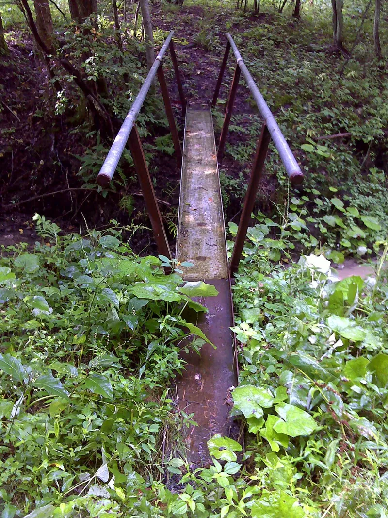
Photo: javajoe6, CC BY-SA 3.0, via Wikimedia Commons
Long bespoke elements are frequently the most visible parts of a project: the continuous balustrade along a circulation route, the cladding rail that sets a facade line, the canopy edge that reads as a single clean stroke. They are also the elements most likely to be drawn as though they were short. Thermal movement is not a defect in the steel; it is a predictable behaviour. The risk arises when the drawing package gives that behaviour nowhere to go.
Why length changes the question
A short bracket can be restrained at every bolt and rarely complain. A 40 m handrail cannot. Using the usual illustrative coefficient for steel, a 40 m run subjected to a 20 °C swing will attempt to change length by roughly 10 mm. A wider swing gives a larger figure. Those numbers are not a design method, but they explain why the detail that works at 2 m is not transferable to 40 m.
UK external metalwork also sees conditions that a simple air-temperature figure may understate. Dark finishes in direct summer sun can run appreciably warmer than the surrounding air, while clear winter nights can take exposed sections below it. The structural engineer should set the design temperature range for the element; the fabricator’s task is to detail so that the resulting movement can occur without overstressing the connections or disturbing adjacent construction.
Restraint is a decision, not a default
A continuous run needs a deliberate arrangement of fixed and guided points. The fixed point provides the longitudinal datum and takes the thermal movement load. Guided points allow movement along the run while controlling it laterally. If every bracket is bolted hard to the structure, the run has no datum and no release; the movement is shared unpredictably between fixings, welds and the element itself.
Slotted connections are one common release mechanism, but a slot is only useful if the drawing states its length, orientation, bolt diameter, washer arrangement and tightening regime. A slot that is drawn but not dimensioned invites the workshop to make a reasonable assumption and the site team to make a different one. The same applies to bearing pads, sleeve details and cover plates: if they are needed to let the joint work, they belong on the fabrication drawing, not in a site instruction.
Where unplanned restraint shows up
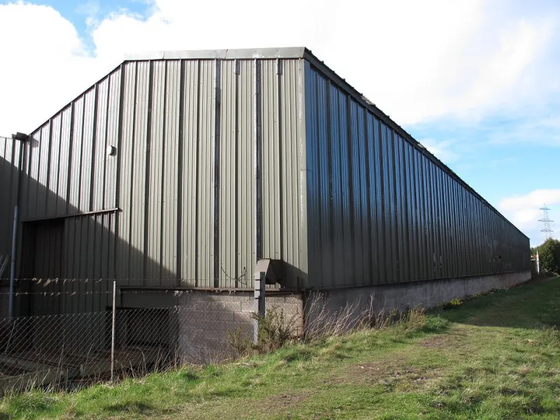
Workshop and site examples tend to repeat. A continuous balustrade welded to every post base plate may appear robust until the run is exposed to a seasonal swing; the fixed points then fight each other and the visible symptom can be a bowed rail, a cracked weld at a stiffer connection or a loosened anchor. A canopy fascia bolted hard to columns at both ends may transfer movement into the column line, producing failed fixings or a noisy interface as surfaces slip under load. Cladding rails butted tight without a movement joint can buckle at a splice or distort the sheet line.
Noise is often the first clue. A rail that ticks or groans as it warms is not settling in; it is telling the building that a sliding interface is not sliding as intended. By the time the symptom appears on site, the economical correction has usually passed. The drawing stage is where the route for movement is either created or closed off.
What should be visible before release
A trade buyer does not need to redesign the connection, but the fabrication package should show that movement has been addressed. Before release, look for a movement joint schedule or marked joint locations on the general arrangement. Check that fixed and guided points are identified, not left to the fitter. Confirm that slots are dimensioned with their orientation and that the bolt, washer and clearance details are stated. Look for any bearing or isolation pad, cover plate or sleeve that the joint depends on.
The drawings should also state the installation condition. If the joint is set at one temperature and the run is installed at another, the setting-out allowance needs to be understood. The sequence matters where a long element is connected to other trades: a rail installed after the facade is set may need a different tolerance from one installed before it.
A short release checklist for trade buyers
- Are fixed and guided points marked on the fabrication drawings?
- Is the design temperature range stated, with the source of that figure identified?
- Are movement joints located, dimensioned and scheduled?
- Do slotted connections show slot length, orientation, bolt size, washers and tightening requirements?
- Are bearing pads, sleeves or cover plates called up where the joint relies on them?
- Is the installation temperature or setting-out allowance stated?
- Are adjacent interfaces checked so that movement is not transferred into finishes, cladding or fixings?
- Has the workshop confirmed that the detail can be fabricated and assembled as drawn?
Thermal movement is one of the few uncertainties in bespoke metalwork that can be largely removed by paperwork. The steel will still expand and contract; the question is whether it does so through a designed joint or through a weld that was never meant to take the load. For 2026 projects, the sensible release gate is simple: if a long run has no agreed route for movement, the drawing is not ready for the saw.